Size:
3.97
MB
〈Catalog〉Panel mount type water quality measuring instruments 48/96 Series
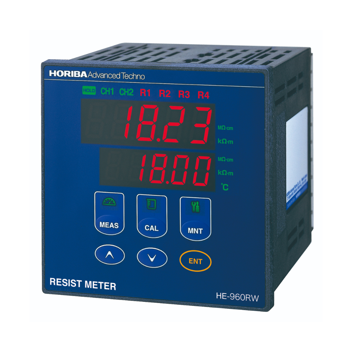
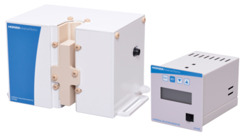
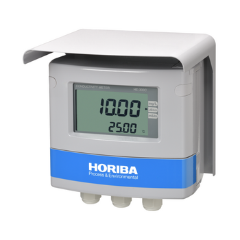
Panel-mount type 2-channel electric resistivity meter (resistivity meter)
A high-grade resistivity meter that significantly improves critical temperature compensation performance for resistivity measurements of UPW (ultra-pure water) and high-temperature pure water, through adopting a newly designed temperature measurement circuit. Highly stable resistivity measurements are achieved through resistance to changes not only in water temperature, but also in ambient temperature.
![]()
![]()
![]()
![]()
![]()
![]()
Enables measurements with minimal error
Measurements are affected less by ambient temperature and sample temperature, enabling accurate measurements with less error.
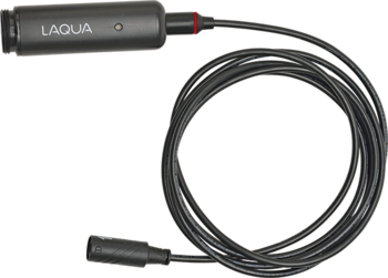
Highly responsive temperature sensor
Helps to minimize fluctuations in measurement values due to delayed temperature compensation in the event of sudden changes in water temperature.
We provide equipment and sensor calibration services
Temperature sensor offset calibration is offered as well as transmitter and sensor combination calibration services. *Option
2-channel specification
Allowing measurement at 2 points, and capable of displaying salt removal rate.
| Product name | Industrial 2-channel specific resistance meter | |||||
|---|---|---|---|---|---|---|
| Model | HE-960RW | |||||
| Measurement method | Electrode type (2-electrode method) | |||||
| Sensor input | 2 channels (for concurrent measurement with sensors isolated each other) | |||||
| Cell constant | 0.01/cm | |||||
| Temperature sensor specifications | Platinum resistance 1000 Ω/0℃ | |||||
| Measuring range | Measurement unit | kΩ•m | 0 to 20.0 | 0 to 200.0 | 0 to 1000 * | |
| MΩ•cm | 0 to 2.00 | 0 to 20.00 | 0 to 100.0 * | |||
| *: Measurable without temperature compensation | ||||||
| Temperature | 0℃ to 100℃ (The number of digits after the decimal point is selectable from one and two. The range of measurements is −20℃ to 120℃.) | |||||
| Desalination rate | 0% to 100% | |||||
| Temperature: 0℃ to 100℃ (Select your desired decimal point from 0, 1, and 2 digits.) | ||||||
| Repeatability | Within ±0.1% of the full scale (in equivalent input) | |||||
| Linearity | Within ±0.5% of the full scale (in equivalent input) | |||||
| Transmission output | Number of outputs: 2 4 mA to 20 mA DC/0 mA to 20 mA DC, input/output isolated type Maximum load resistance: 900 Ω Transmission output range: Freely selectable within the measurement range (Negative terminals of each transmission output channel are connected inside and thus have the same electric potential.) | |||||
| Contact output | Number of outputs: 4 Alarm contact outputs (R1, R2, and R3) Contact type: relay contact, SPST (1a) Contact rating: 240 V AC, 3 A and 30 V DC, 3 A (resistance load) Contact function: selectable from the upper/lower limit action (ON/OFF control), delay, and hysteresis Selectable from the selected measurement, anomaly alarm, and maintenance. Alarm contact output (R4) Contact type: relay contact, SPDT (1c) Contact rating: 240 V AC, 3 A and 30 V DC, 3 A (resistance load) Contact function: selectable from the upper/lower limit action (ON/OFF control), delay, and hysteresis Selectable from the selected measurement, anomaly alarm, and maintenance. (However, R1 and R2, and R3 and R4 share the common contacts respectively.) | |||||
| Calibration function | Specific resistance: Based on the specified compensation coefficient for cell constant (parameter input) Temperature: Calibrated by comparing with the reference thermometer | |||||
| Communication output | RS-485 input/output | |||||
| Transmission output hold feature |
| |||||
| Self-diagnosis function |
| |||||
| Temperature compensation |
| |||||
| Temperaturecompensated range | 0℃ to 100℃ | |||||
| Extra deionized water specific resistance selection | Measurement unit | kΩ•m | 182.3 (standard), 181.8, 182.4 | Select from options shown on the left. | ||
| MΩ•cm | 18.23 (standard), 18.18, 18.24 | |||||
| Clipping function | When the measured value is above the upper limit of the measurement range derived from the specified specific resistance, the specified resistance is used as the measured value. | |||||
| Ambient temperature | −5℃ to 45℃ | |||||
| Relative humidity | 20% to 85% (without dew condensation) | |||||
| Storage temperature | −25℃ to 65℃ | |||||
| Power supply | Rated voltage 100 V to 240 V AC, 50/60 Hz, 10 VA (max.) | |||||
| Structure | Indoor-use panel installation type Panel case: ABS, Terminal: PBT Panel: IP65 dust and water proof structure | |||||
| Protective structure | Panel: IP65 (IEC60529, JIS C0920) Rear case: IP20, Terminal:IP00 Class II device (IEC61010-1) Pollution level 2 (IEC61010-1) | |||||
| Conforming standards | CE Marking | EMC Directives: EN61326-2-3 Low Voltage Directive: EN61010-1 RoHS Directive: EN50581 | ||||
| FCC Rule | FCC Part15 | |||||
| External dimensions | 96 (W) mm × 96 (H) mm × 115 (D) mm Case depth: approx. 105 mm (when panel-mounted) | |||||
| Mass | Approx. 550 g | |||||
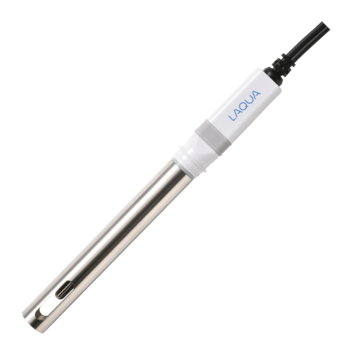
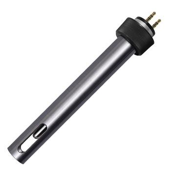
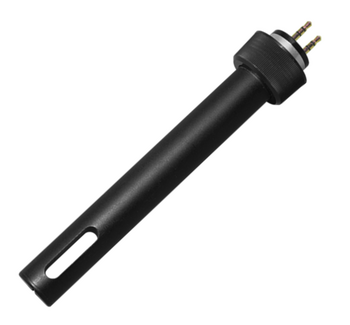
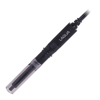
| Compatible sensors | ERD/ERF-series specific resistance sensor, cell constant 0.01/cm | |||||
Do you have any questions or requests? Use this form to contact our specialists.
 Y071L")
1.41 mS/cm Conductivity Standard Solution
 Y071H")
12.9 mS/cm Conductivity Standard Solution
Conductivity Cell for Ultra Pure Water Measurement

Fiber Optic Type Chemical Concentration Monitor
Optical Fiber Type Hot Phosphoric Acid Concentration Monitor
Non-Contact Chemical Concentration Monitor

Field-installation type water quality measuring instruments

Field-installation Type Fluoride Ion Concentration Meter

Field-installation type ammonia nitrogen meter
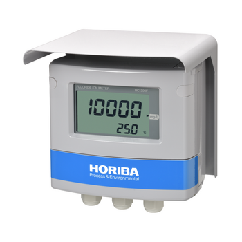
Field-installation Type Fluoride Ion Concentration Meter

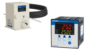
Field-installation type dissolved oxygen meter (DO meter)

Field-installation type optical dissolved oxygen meter (DO meter)

Field-installation type dissolved oxygen meter (DO meter)
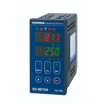
Panel-mount type dissolved oxygen meter (DO meter)

HF (Hydrofluoric Acid) DO (Dissolved Oxygen) Monitor / Pure Water DO (Dissolved Oxygen) Monitor
Dissolved Oxygen Concentration Monitor Series for Semiconductor Manufacturing

Field-installation type electric conductivity meter (conductivity meter)

Field-installation type electric conductivity meter

Field-installation type electric resistivity meter (resistivity meter)
Field-installation type electrical conductivity meter (conductivity meter)
Field-installation type water quality measuring instruments
Field-installation type dissolved oxygen meter (DO meter)
Field-installation type dissolved oxygen meter (DO meter)
Panel-mount type dissolved oxygen meter (DO meter)
HF (Hydrofluoric Acid) DO (Dissolved Oxygen) Monitor / Pure Water DO (Dissolved Oxygen) Monitor
Dissolved Oxygen Concentration Monitor Series for Semiconductor Manufacturing
Field-installation type electric conductivity meter (conductivity meter)
Field-installation type electric conductivity meter
Field-installation type electric resistivity meter (resistivity meter)
Field-installation type electrical conductivity meter (conductivity meter)
Field-installation type electric resistivity meter (resistivity meter)
Panel-mount type conductivity meter (conductivity meter)
Carbon Sensor Conductivity Meter (Low concentration type)
Panel-mount type conductivity meter (conductivity meter)
Panel-mount type resistivity meter (resistivity meter)
Resistivity Meter for Semiconductor Cleaning Processes
Citric Acid Monitor
Panel-mount type 2-channel conductivity meter (conductivity meter)
KOH Monitor
Wide range TMAH Concentration Monitor
High Precision TMAH Concentration Monitor
Carbon Sensor Conductivity Meter (High concentration type)
Panel-mount type conductivity meter
Carbon Sensor Conductivity Meter
Flat Carbon Sensor Conductivity Meter
Carbon Sensor Resistivity Meter
2-Channel Resistivity Meter
Low Concentration Monitor- Sulfuric Acid/Hydrogen Peroxide
HF / HCl Concentration Monitor
Low Concentration Type HF/HCl/NH3 Concentration Monitor
Field-installation type ORP meter
Field-installation type ORP meter
Panel-mount type ORP meter
Field-installation type polarographic residual chlorine meter
Field-installation type residual chlorine meter
Panel-mount type galvanic residual chlorine meter
On-line TOC analyzer


")
")
")
")
")
")
")
")
")
")


")
")
")
")
")
")

")
")
")
")
")
")
")


")
")
")
")
")
")
")


")


,HE-960LC")


")
")


