Size:
5.24
MB
〈Catalog〉Industrial Water Quality Measuring Instruments

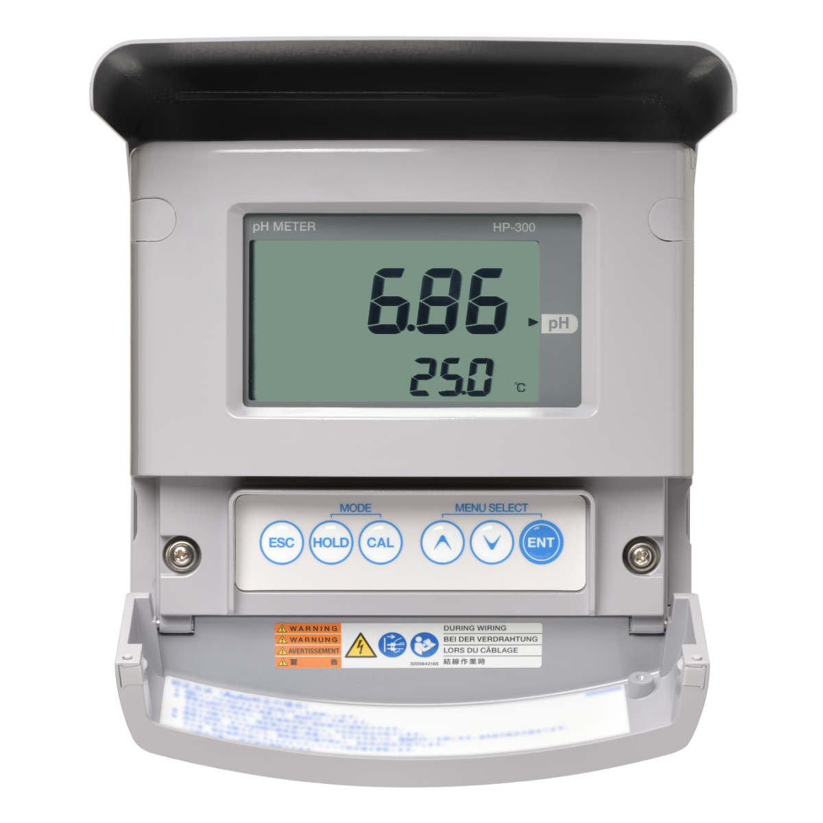
Field-installation type pH meter
Suitable for pH monitoring and control in various production processes, as well as wastewater treatment and other applications. We offer a wide range of electrodes and cleaning devices to accommodate a variety of samples.
![]()
![]()
![]()
![]()
![]()
![]()
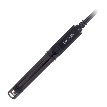
Lineup of a wide range of electrodes
A wide variety of electrodes are offered to cater to different needs.
Comprehensive range of cleaning devices.
A diverse lineup of cleaning devices are offered. Particularly, ultrasonic cleaners are advantageous as they do not require water or air, making them convenient for retrofitting existing HP-300 installations on site. The drop-in type of cleaning device, which fits into a holder, offers ease of maintenance.
| Product name | pH meter | |||
|---|---|---|---|---|
| Model | HP-300 | |||
| Combined sensor | Glass electrode | |||
| Measurable range | pH | pH0 to pH14 (display range: pH−1 to pH15) | ||
| Temperature | 0℃ to 100℃ Display range when automatic detection capability for each temperature sensor type is used: −10℃ to 110℃ Display range when temperature sensor type is manually set: −20℃ to 130℃ | |||
| Display resolution | pH | 0.01 pH | ||
| Temperature | 0.1℃ | |||
| Performance | pH | Repeatability | Within ±0.03 pH (response for equivalent input) | |
| Linearity | Within ±0.03 pH (response for equivalent input) | |||
| Temperature | Repeatability | ±0.3℃ (response for equivalent input) | ||
| Linearity | ±0.3℃ (response for equivalent input) | |||
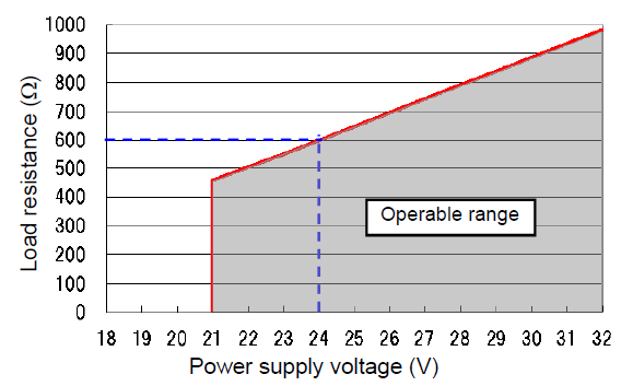
| Transmission output | Output type | 4 mA to 20 mA DC: input/output isolated type | ||
| Load resistance | Maximum: 600Ω Case of 24 V DC power supply (*Note 1) | |||
| Linearity | Within ±0.08 mA (output only) | |||
| Repeatability | Within ±0.08 mA (output only) | |||
| Output range | pH: Selection from preset ranges or free range input within measuring range. | |||
| Occasional out for error | Hold or burnout to either 3.8 mA or 21 mA | |||
| Transmission hold | In the maintenance mode, transmission signal is held at the latest value or preset value. In the calibration mode, transmission signal can be alive or held. | |||
| Contact input | Number of input points | 1 | ||
| Contact type | No-voltage "a" contact for open collector | |||
| Conditions | ON resistance: 40 Ω Open voltage: 1.2 V Short-circuit current: 21 mA DC max. | |||
| Contact function | External input for transmission holding. | |||
| Temperature compensation | Applicable temperature element | Platinum resistor: 1 kΩ (0℃) | ||
| Positive relation resistor with temperature :500 Ω (25℃), 6.8 kΩ (25℃), 10 kΩ (25℃) | ||||
| Element selection method | Automatic temperature sensor type detection or manual selection (No temperature element is selectable) | |||
| Temperature compensation range | 0℃ to 100℃ | |||
| Temperature calibration | 1 point calibration comparing reference thermometer | |||
| Calibration | Calibration method | Auto or basic (manual) calibration | ||
| Number of calibration points | Selectable from 1, 2, and 3 points | |||
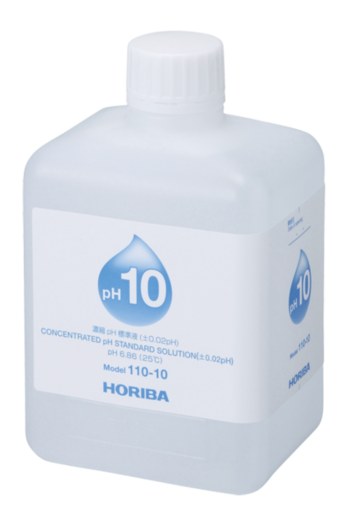
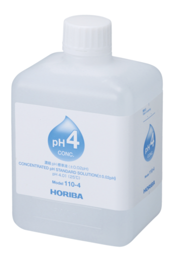
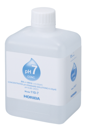
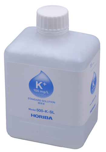
| Kinds of standard solutions | pH 2, 4, 7, 9, 10 | |||
| Any pH standard solution (with difference of 2 pH or more) for basic calibration | ||||
| Additional capabilities | Automatic detection of kind of standard solution | |||
| Automatic detection of electric potential stability | ||||
| Automatic detection of calibration failure (asymmetry potential, sensitivity, or response time) | ||||
| Calibration history (asymmetry potential, sensitivity, and number of days elapsed after last calibration) | ||||
| Self-check | Calibration error | Asymmetry potential error, sensitivity error, and response time error | ||
| Temperature calibration error | ||||
| Standard solution detection error | ||||
| Electrode diagnostic error | Cracking of glass response membrane | |||
| Reference electrode impedance error (only applicable for differential circuit mode with a liquid ground electrode) | ||||
| Temperature sensor short-circuit, temperature sensor disconnection, and deviation from temperature measurement range | ||||
| Meter error | CPU, ADC, and EEPROM errors | |||
| Operating temperature range | −20℃ to 60℃ (without freeze) | |||
| Operating humidity range | Relative humidity: 5% to 90% (without condensation) | |||
| Storage temperature | −25℃ to 65℃ | |||
| Power supply | Rated voltage | 24 V DC (operating voltage range: 21 V to 32 V DC) (*Note 1) | ||
| Power consumption | 0.6 W max. | |||
| Compatible standards | CE marking | Compatible standards | EMC directive | EN61326-1 |
| RoHS Directive | EN50581 | |||
| Immunity | Industrial electromagnetic environment | |||
| Electostatic discharge | IEC61000-4-2 | |||
| Electromagnetic field of radiated radio frequency | IEC61000-4-3 (*Note 2) | |||
| Electric fast transient/burst | IEC61000-4-4 (*Note 2) | |||
| Surge | IEC61000-4-5 (*Note 3) | |||
| Conducted interference induced by radio frequency | IEC61000-4-6 (*Note 2) | |||
| Emission | Class A | |||
| Radiated disturbance | CICPR 11 CLASS A | |||
| FCC rules | Part15 CLASS A | |||
| Structure | Installation | Outdoor installation type | ||
| Installation method | Mount on 50 A pole or wall | |||
| Protection code | IP65 | IEC60529, JIS C0920 | ||
| Case material | Aluminum alloy (coated with epoxy-denatured melamine resin) | |||
| Material of fittings | SUS304 | |||
| Material of hood | SUS304 stainless steel (coated with epoxy-denatured melamine resin) | |||
| Material of window | Polycarbonate | |||
| Display element | Reflective monochrome LCD | |||
| External dimensions | 180 (W) mm × 155 (H) mm × 115 (D) mm (excluding mounting brackets) | |||
| Mass | Main body: Approx. 2.8 kg cover and mounting brackets: Approx. 1 kg | |||
Do you have any questions or requests? Use this form to contact our specialists.

Fiber Optic Type Chemical Concentration Monitor
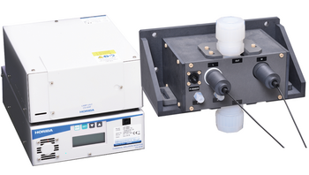
Optical Fiber Type Hot Phosphoric Acid Concentration Monitor
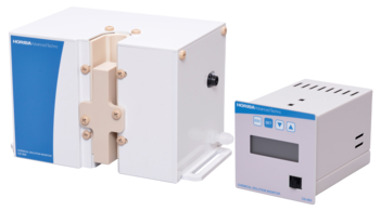
Non-Contact Chemical Concentration Monitor

Standard type

For measurement of low-conductivity water and non-aqueous solvents.

Field-installation type water quality measuring instruments

Field-installation Type Fluoride Ion Concentration Meter

Field-installation type ammonia nitrogen meter
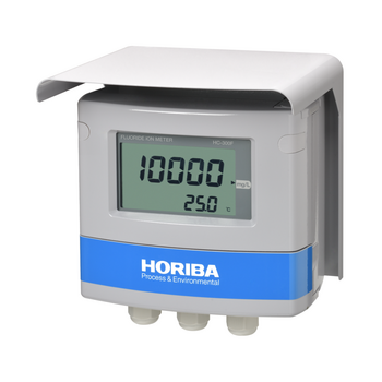
Field-installation Type Fluoride Ion Concentration Meter

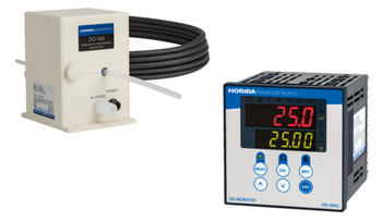
Field-installation type dissolved oxygen meter (DO meter)

Field-installation type optical dissolved oxygen meter (DO meter)

Field-installation type dissolved oxygen meter (DO meter)

Panel-mount type dissolved oxygen meter (DO meter)
HF (Hydrofluoric Acid) DO (Dissolved Oxygen) Monitor / Pure Water DO (Dissolved Oxygen) Monitor
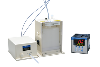
Dissolved Oxygen Concentration Monitor Series for Semiconductor Manufacturing

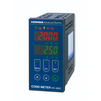
Field-installation type electric conductivity meter (conductivity meter)

Field-installation type electric conductivity meter

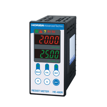
Field-installation type electric resistivity meter (resistivity meter)
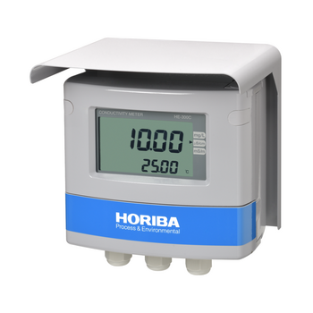
Field-installation type electrical conductivity meter (conductivity meter)

Field-installation type electric resistivity meter (resistivity meter)
Panel-mount type conductivity meter (conductivity meter)

Carbon Sensor Conductivity Meter (Low concentration type)

Panel-mount type conductivity meter (conductivity meter)

Panel-mount type resistivity meter (resistivity meter)
Resistivity Meter for Semiconductor Cleaning Processes

Citric Acid Monitor
")
")
")
")
")
")
")
")
")

")
")
")
")
")
")

")
")
")
")
")

")
")


 Y021L")
 Y071L")
 Y071H")
 Y021H")
")
")
")
")

")
")
")
")
")
")
")
")
")
")
")
")
 5002S-10C")


 6583S-10C")


 6560S-10C")