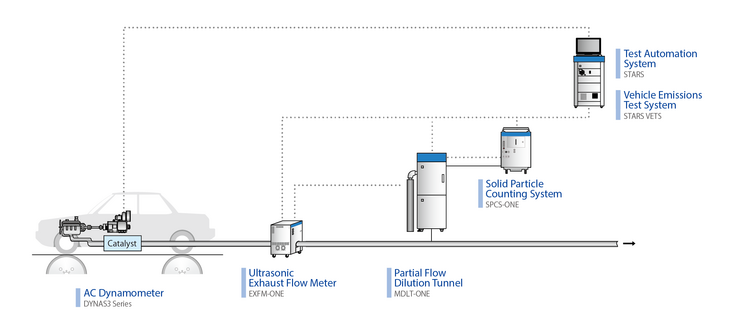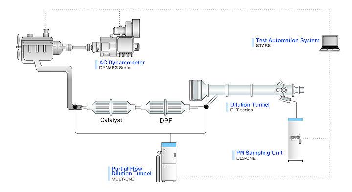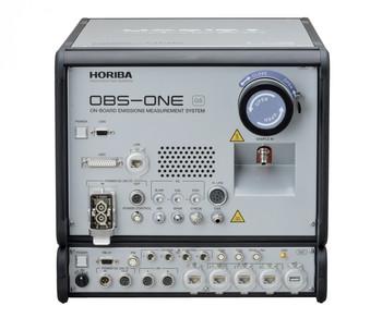
| System outline | ||||||
| PM sampling method | Partial flow dilution method | |||||
| Control modes for dilution | Proportional sampling mode (Const. split ratio)/ Fixed dilution ratio mode (Const. dilution ratio)/ Fixed flow rate mode (Manual control) | |||||
| Control methods for dilution | ・Real-time control based on analog input of exhaust flow rate ・Control based on learned pattern of exhaust rate | |||||
| Required signal for gas sampling | Isolated analog signal (0 to 10 V) | |||||
| Flow rate of diluted gas | 25 to 80 L/min*1 (under the condition of 20 °C and 101.3 kPa) | |||||
| Accuracy of dilution ratio | Within ± 5 % (Confirmed by measuring CO₂) When dilution ratio=15 rate at 20 °C and 101.3 kPa: 53 to 80 L/min | |||||
| PM mass calculation*2 | PM mass (in g/test or g/kWh) can be calculated and saved, based on integrated values of flow rated and dilution ratio. | |||||
| Configurations | ||||||
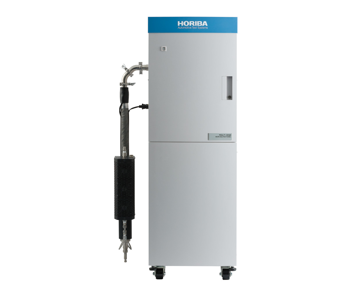
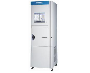
| System configuration | ・Main unit: Dilution-tunnel unit ・Operation unit: PC, monitor, keyboard and mouse (table is not included) | |||||
| Utilities | ・Purified air: for dilution gas, 400 to 700 kPa, oil free, at least 100 L/min (at 20 °C and 101.3 kPa) | |||||
| Power supply voltage and frequency | ・Main unit: 100/110/120/200/220/230/240 V AC, 50/60 Hz, single phase ・Operation unit: 100/110/120/200/220/230/240 V AC, 50/60 Hz, single phase | |||||
| Power requirements | Main unit: Max. 3.0 kVA / Operation unit: Max. 0.5 kVA | |||||
| Dimensions | ・Main unit: 570 (W) × 730 (D) × 1700 (H) mm ・Space for operation unit: 900 (W) × 500 (D) mm (table is not included) | |||||
| Mass | Main unit: Approx. 300 kg (excluding operation unit) | |||||
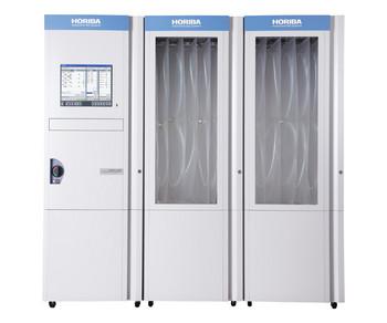
| Number of filter lines | Max. 6 lines (5 for sample, 1 for bypass) | |||||
| Type of filter holder | ・φ70 mm type: actual PM sampling area φ60 mm, with back-up filter ・φ47 mm type: actual PM sampling area φ38.8 mm*1, with back-up filter*1 | |||||
| Operating conditions | ||||||
| Sampling Pressure | Between atmospheric pressure and up to 40 kPa Back pressure of exhaust line: Less than 1 kPa | |||||
| Options | ||||||
| Filter auto-changer*3 | Changer for automatic replacement of PM filter (φ 47 mm) | |||||
| Valve switching | Additional air valve before filter (Replacement of sampling filter on bypass mode) | |||||
| HOST interface*3 | LAN communication using a 10 Base T port Conforms to IEEE802.3 (ISO880 2/3) | |||||
| Conditioner for dilution air / Compressor | ||||||
*1, For the filter face velocity in the regulations (less than 100 cm/s), the flow rate for the φ47 mm filter must be 65 standard L/min.
*2, Input the amount of PM collected on filter to calculate PM mass. It is necessary to input engine output (kW) to calculate the PM mass engine output (g/kWh).
*3, Please contact HORIBA, when you order.
